Electrical panel with control system
The electrical panel of the WS-SMART-HG system, with the heating plant control system. The WS-SMART-IO modules connect to it and are chained from box to box, Modbus bus and power supply included. Web supervision, BACnet or Modbus to the existing BMS.
- WS-SMART-HG control system
- Daisy-chained WS-SMART-IO modules
- BACnet / Modbus
- Web-based supervision
Coming soon. Announced: CE conformity assessment in progress. Availability and lead time confirmed in the quotation. For sizing, call +41 27 326 60 00.
Example · WS-HG panel and daisy-chained modules
The WS-HG panel houses the control unit, the Modbus RTU master, and the outgoing feeds of the WS-SMART-IO modules: Modbus RTU bus and 24 VAC on one side, protected 230 V on the other, daisy-chained from module to module up to the last one.
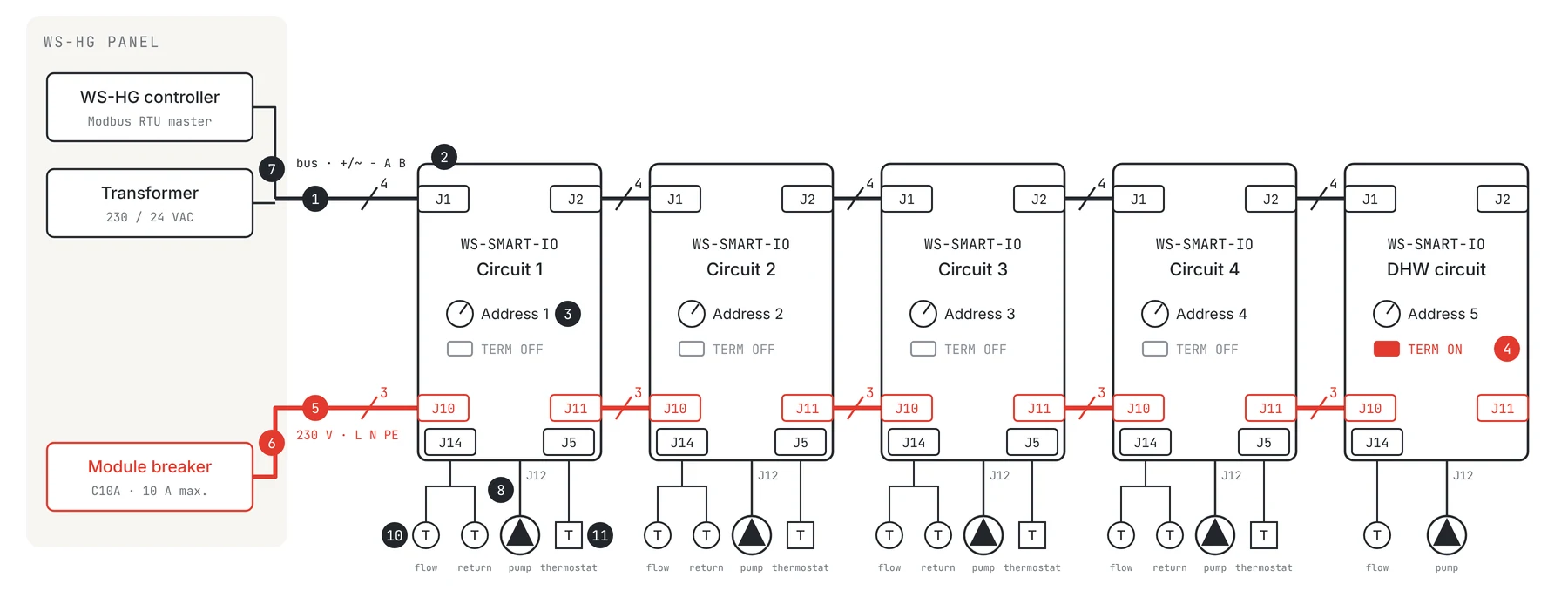
- 1Bus daisy-chained from module to module, 4 wires: +/~ and − carry 24 VAC/VDC, A and B Modbus RTU. A to A, B to B, never crossed.
- 2J1: bus in, from the panel or the previous module. J2: out to the next module.
- 3Set the address with the power off, one per module, no duplicates: 1 to 4 for the heating circuits, 5 for the DHW circuit. Position 0: the module does not respond.
- 4TERM jumper (120 ohms) ON at the last module of the line only, OFF everywhere else.
- 5230 V daisy-chained, 3 wires L, N, PE: J10 in, J11 out, terminals in parallel.
- 6Module 230 V line protected in the panel by a circuit breaker of 10 A max. Module fuses F1 and F3: 6 A.
- 724 VAC from the panel transformer; each module draws 70 mA and accepts 19.2 to 28.8 V.
- 8J12: circulator supply, current measured. J13: pump enable relay.
- 9Up to 15 modules per bus. Modbus RTU: 19 200 Bd, even parity, 1 stop bit.
- 10J14: PT1000 sensors, flow on RTD 1 (terminals 1-2), return on RTD 2 (terminals 3-4). DHW circuit: flow sensor only. Cable G51 1 × 2 × 0.8 mm per sensor.
- 11J5: circuit safety thermostat, volt-free CO-NC contact on DI 1 (terminals 1-2), reported as a fault. Cable G51 1 × 2 × 0.8 mm. No thermostat on the DHW circuit.
- In red: 230 V and TERM jumper set to ON
What the panel brings together
The WS-HG controller, Modbus RTU master, runs the WS-SMART-HG control system: up to 6 heating circuits, 2 DHW cylinders, district heating or a generator cascade.
A 230 / 24 VAC transformer for the module bus, a circuit breaker of 10 A max. for their 230 V line.
Modules are chained from box to box, bus and 230 V included: no more harness to bring back group by group to the cabinet.
Fully web-based interface, local or secure remote access; BACnet and Modbus to the existing BMS.
The panel
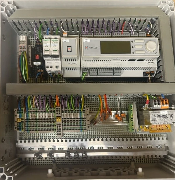
Wired WS-HG electrical panel, enclosure open: at the top, circuit breakers, module and controller with display and control knob, Wellset logo; in the middle, terminal blocks, lever connectors and 230 / 24 V transformer; at the bottom, cable clamping rail and cable entries
The controller and its connections
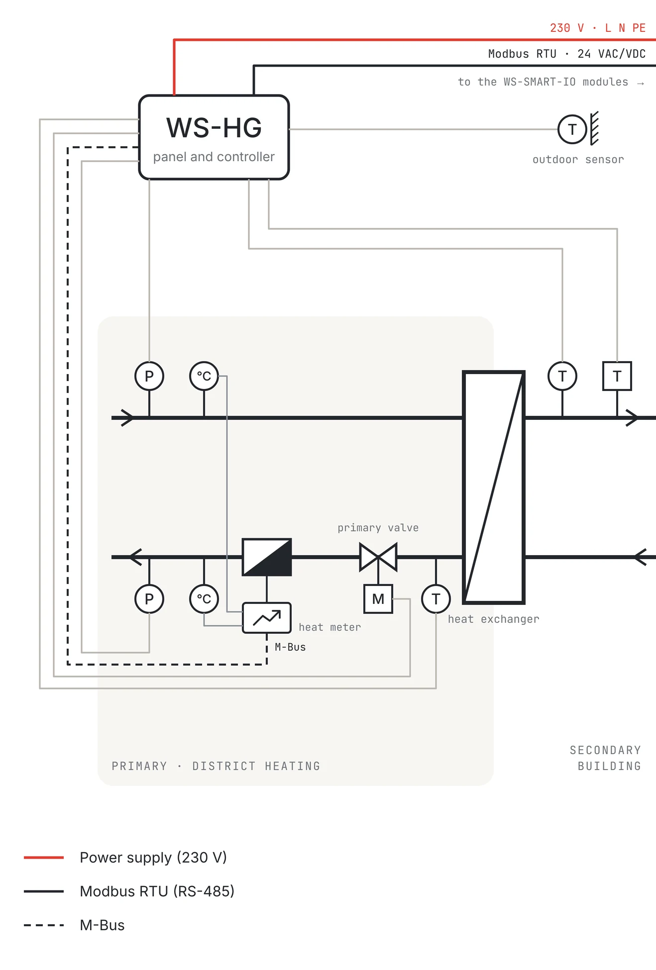
WS-HG part of the WS-SMART-HG topology: the WS-HG controller, from which the 230 V supply and the Modbus RTU (RS-485) bus run to the modules, linked via M-Bus to the energy meter and wired to the outdoor sensor, the pressure and temperature sensors and the motorised valve of the district heating heat exchanger; legend of the three links
Specifications
| Function | Heating plant electrical panel with the WS-SMART-HG control system |
|---|---|
| Control | That of WS-SMART-HG: up to 6 heating circuits, 2 DHW cylinders, district heating, generator cascade |
| Expansion | WS-SMART-IO modules connected to the panel and chained from box to box: Modbus RTU bus and power supply |
| Communication | BACnet and Modbus, integration into an existing BMS |
| Supervisory system | Fully web-based interface, local access or secure remote access |
|---|---|
| Manufacturer | Wellset |
| Restocking lead time | Confirmed in the quotation |