Heating plant control
Turnkey boiler-room control for refurbishment: it replaces an end-of-life controller without touching the existing hydraulics. Up to six heating circuits, two DHW boilers, district heating, generator cascade. Wiring through chained WS-Smart-IO modules; web supervision, BACnet or Modbus to the existing BMS.
- 6 heating circuits
- 2 DHW cylinders
- District heating
- BACnet / Modbus
Pre-production series: CE conformity assessment in progress. Availability and lead time confirmed in the quotation. For sizing, call +41 27 326 60 00.
Example · district heating substation
Connected to district heating, the substation delivers heat to the building's heating circuits, and they are what sets the return temperature. WS-SMART-HG measures the primary return and the return of each circuit, reads the heat meter over M-Bus and the actual position of the primary valve, and makes these points available to the network operator's supervision system over BACnet or Modbus.
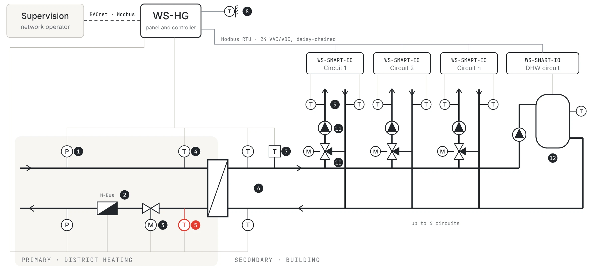
- 1Primary supply and return pressure
- 2Heat meter (M-Bus)
- 3Primary valve, position feedback
- 4Primary supply temperature
- 5Primary return temperature
- 6Secondary temperatures
- 7Secondary safety thermostat
- 8Outdoor temperature
- 9Heating circuit temperatures
- 103-way valve, position feedback
- 11Circulator, current measured
- 12DHW: cylinder and charging pump
- In red: value set by the network operator
What the controller changes
Each actuator reports its real position: a valve turned by hand, jammed or disengaged flags itself.
The circulator output measures current from 0 to 10 A, detection from 0.2 A: a pump that does not start or runs dry is seen at once.
WS-Smart-IO modules are standard Modbus RTU slaves, up to fifteen per bus: a controller with a Modbus RTU master drives them directly, without the WS-HG controller.
Modules are chained from box to box, bus and 230 V included: no more harness to bring back group by group to the cabinet.
The film
A boiler-room controller can be replaced without touching the hydraulics. The film shows the modules chained circuit by circuit, the detection of manually forced valves and stopped pumps, then the Modbus opening. 56 seconds, no sound needed.
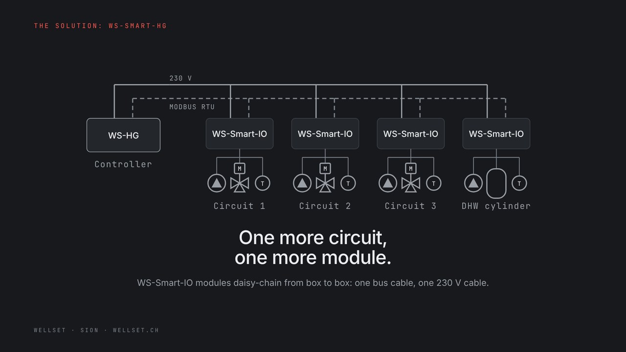 Open the film full screen
The hardware
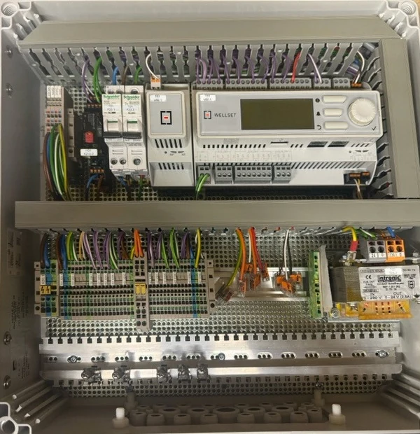

Specifications
| Heating circuits | Up to 6, independent |
|---|---|
| Domestic hot water | 2 cylinders with priority, built-in anti-legionella cycle |
| District heating | 1 or 2 heat exchangers, or conventional heating |
| Heating curves | 2 or 5 points |
| Heat sources | Cascade of mixed heat sources: heat pump, gas, biomass, electric backup |
| Summer / winter changeover | Automatic |
| Optimisation | Flow temperatures adjusted to actual demand |
| Power management | Power limitation and load peak shaving |
| Valves | Position feedback: detection of manual override or local operation |
| Pumps | Control with current sensing for monitoring and maintenance |
| Supervisory system | Fully web-based interface, local access or secure remote access |
|---|---|
| Logging | Integrated data logging and energy monitoring |
| Safety functions | Frost, overheating, sensor fault, pump fault |
| Alarms | Detailed alarms, configurable notifications |
| Cycling | Fewer short cycles: longer heat source life |
| Communication | BACnet and Modbus, integration into an existing BMS |
| Expansion | WS-Smart-IO modules, each: 2 RTD inputs · 2 digital inputs · 2 × 0–10 V actuator outputs · 1 Modbus RTU · 1 × 230 V output to enable the circulating pump |
| Architecture | Modular and expandable, up to several substations |
| Manufacturer | Wellset |
| Restocking lead time | Confirmed in the quotation |
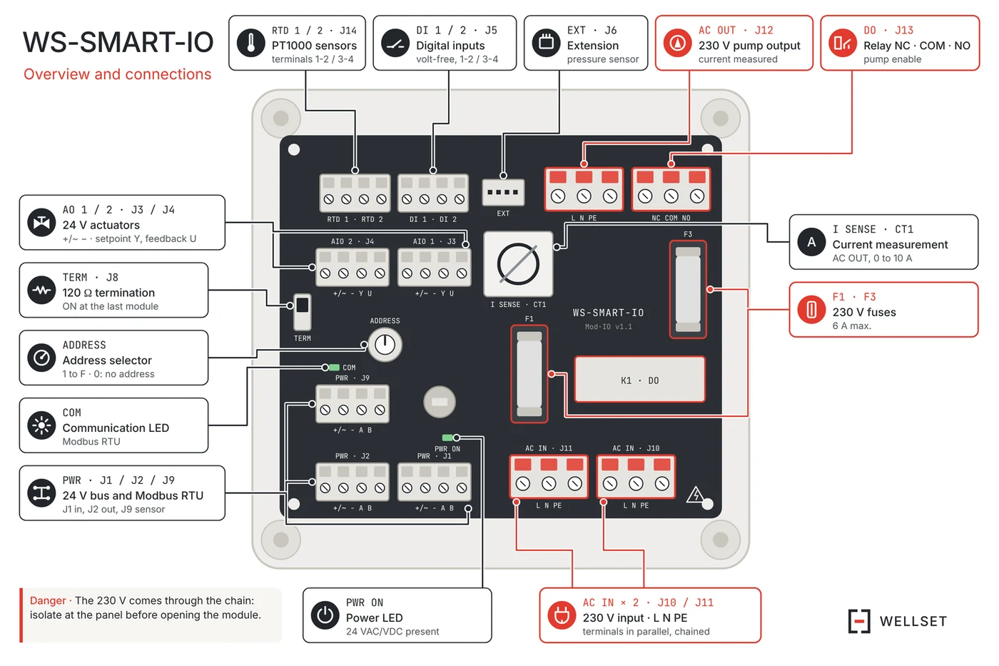
Wiring the WS-SMART-IO modules
The bus arrives on J1 and leaves on J2 (24 VAC, Modbus RTU, A to A, B to B). The 230 V arrives on J10 and leaves on J11; the pump connects to J12 and its enable contact to J13.
PT1000 sensors on J14, safety thermostat on J5, 24 VAC actuator on J3. One address per module, TERM on ON at the last module only. Switch off at the cabinet before opening a module: the 230 V arrives through the chain.
52 seconds, no sound.