
Remote input/output module for air handling units
Remote input/output module, mounted as close as possible to the installation. On an air handling unit: two temperature sensors, two dry contacts, two actuators, one switched 230 V output with current measurement. Modules are chained from box to box, up to fifteen on one bus. It is also the I/O building block of the WS-SMART-HG controller.
Pre-production series: EU declaration of conformity of 5 Oct 2026. Availability and lead time confirmed in the quotation. For sizing, call +41 27 326 60 00.
Specifications
| Temperature inputs | 2 PT1000 sensors (RTD 1, RTD 2),−25 to +50 °C, ±0.5 °C |
|---|---|
| Digital inputs | 2 potential-free inputs (DI 1, DI 2), dry contacts |
| Actuator channels | 2 channels: 0–10 V setpoint, 0–10 V position feedback, 24 V supply |
| Pump output | AC OUT: switched 230 V, with current measurement and protection |
| Relay output | Changeover contact NC – COM – NO on the DO connector |
| Current measurement | 0 to 10 A on the AC IN / AC OUT circuit, detected from 0.2 A |
| 230 V input | AC IN: distribution daisy-chained from module to module, 250 V AC, 10 A max |
| Power supply | 24 V AC or DC (19.2 to 28.8 V), 70 mA, daisy-chained with the bus |
| Communication | Modbus RTU, 19 200 baud, even parity; 15 modules and 50 m of bus at most |
| Addressing | 16-position rotary selector, 120 Ω termination by jumper |
| Expansion | EXT connector: differential pressure sensor ±2490 Pa |
| Diagnostics | One LED per channel: PWR, COM, DI 1–2, RTD 1–2, I SENSE, AIO 1–2 |
| Protection | Two fuses on the AC circuits, 6 A max per the board marking |
| Isolation | AC circuit isolated, 3000 V AC for 1 minute |
| Connection | Pluggable spring-cage terminals:0.5 to 1.5 mm² for signals and bus, 0.75 to 2.5 mm² for the AC circuits |
| Mounting | Legrand Ensto Cubo wall enclosure, 125 × 125 × 75 mm |
| Ingress protection | IP66 |
| Dimensions | Board 113.8 × 98.5 × 34.5 mm |
| Environment | −25 to +50 °C, 0 to 95 % RH |
| Board | Mod-IO v1.1 |
| Manufacturer | Wellset |
| Restocking lead time | Confirmed in the quotation |
The wiring on video
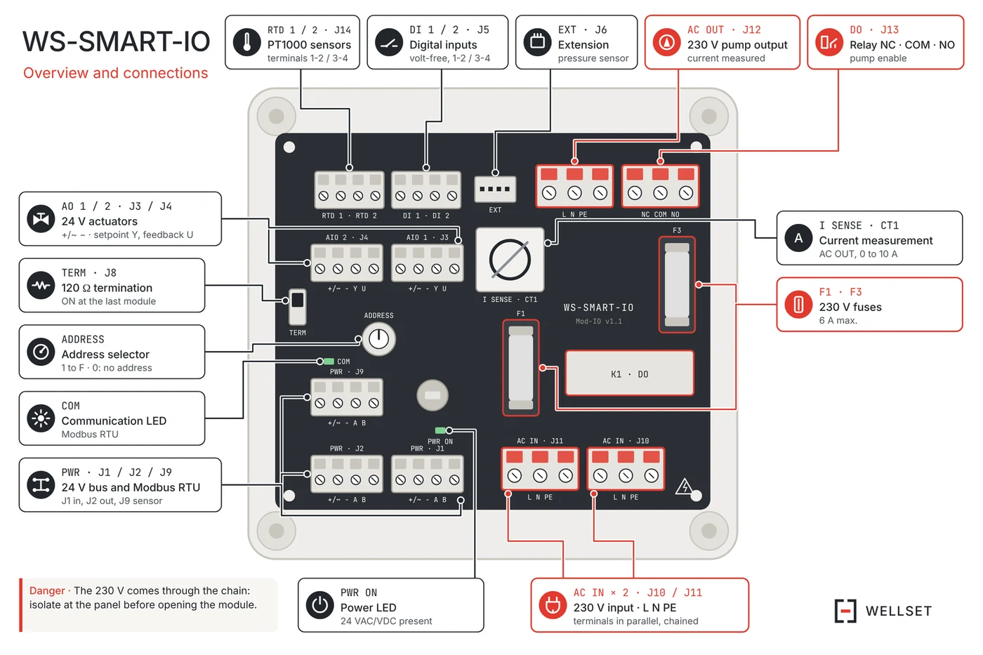
The bus arrives on J1 and leaves on J2 (24 VAC, Modbus RTU, A to A, B to B). The 230 V arrives on J10 and leaves on J11; the pump connects to J12 and its enable contact to J13.
PT1000 sensors on J14, safety thermostat on J5, 24 VAC actuator on J3. One address per module, TERM on ON at the last module only. Switch off at the cabinet before opening a module: the 230 V arrives through the chain.
52 seconds, no sound.