EC-SWAP · schematic diagram
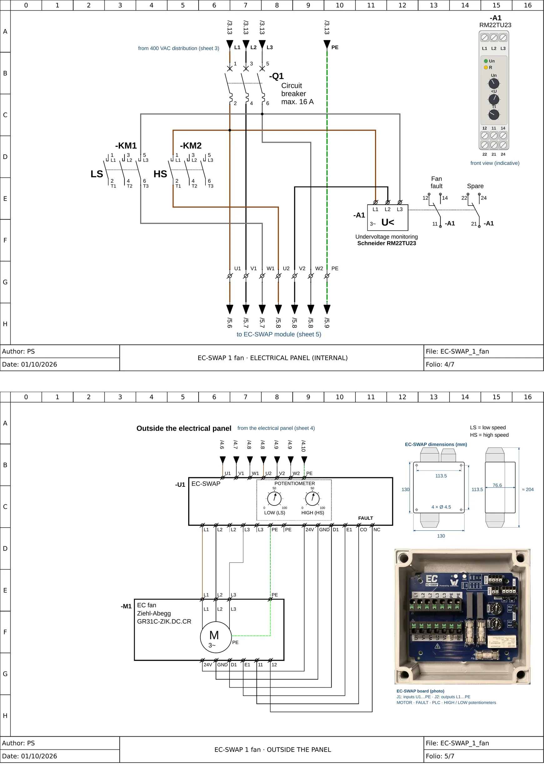
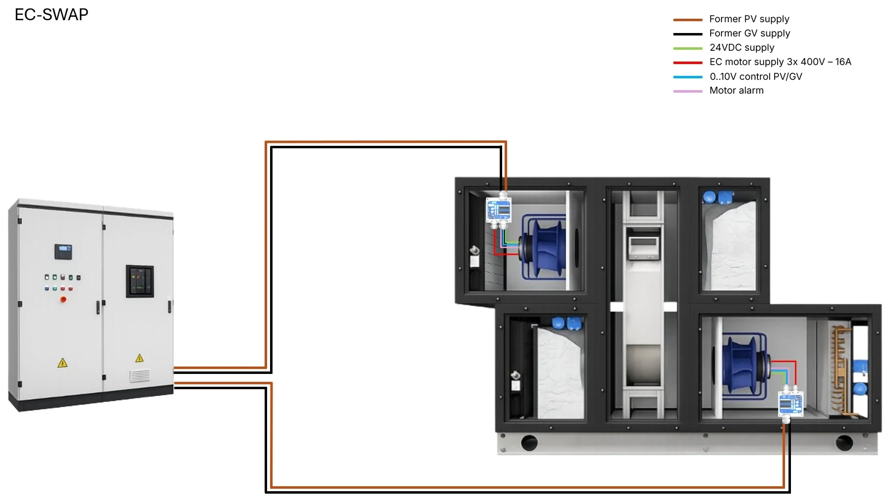
Retrofit of a two-speed fan: the existing control is retained. Five conductors and the protective earth arrive on the board, six with the optional voltage monitor; the board supplies and controls the EC motor. Two views: the circuit diagram and the installation overview. Reference diagram, revision v3.0 · complete diagram in seven sheets, of which sheets 4 and 5 are shown below.
View
Tags
| Tag | Description | Note |
|---|---|---|
| Circuit breaker | Three-pole motor protection switch (existing) | The thermal setting must be adjusted to the EC motor current, which is lower than that of the induction motor. |
| PV | Low-speed contactor (existing) | Only one pole connected: it switches L3 onto W1. |
| GV | High-speed contactor (existing) | Only one pole connected: it switches L1 onto U2. |
| U1 · V1 · W2 | EC-SWAP inputs | Connected to L1, L2 and L3 downstream of the circuit breaker: permanently energised. |
| Voltage monitor | Option, inside the cabinet | Monitors the voltages and provides the “fan fault” contact. The only fault signal source on the cabinet side. |
| EC-SWAP | Wellset interface board | Inputs U1·V1·W1 / U2·V2·W2 + PE · output L1·L2·L2·L3·L3·PE·PE · control 24V · GND · D1 · E1 · fault contact CO · NC. |
| LOW / HIGH | Setpoint potentiometers | LOW sets the low speed (PV), HIGH the high speed (GV), from 0 to 100 %. Marked LOW and HIGH on the board, PV and GV on the diagram. |
| EC fan | Ziehl-Abegg EC motor, M 3~ | Supply 3 × 400 V – 16 A on L1·L2·L3·PE. Control is picked up on its terminal block 24V · GND · D1 · E1 · 11 · 12: 24V, GND, D1 and E1 go to the terminals of the same designation on the EC-SWAP, 11 and 12 to the CO and NC terminals of the fault contact. One EC-SWAP module per air stream. |
Notes and points to confirm
- A dual-flow air handling unit requires two EC-SWAP modules, one per fan, mounted as close as possible to the motor. The circuit diagram applies to one fan.
- EC motor supply: 3 × 400 V – 16 A on L1·L2·L3·PE. The board also distributes the 24 V DC, the speed setpoint and the fault signal, on the motor's control terminal block.
- Output terminal block of the board: seven terminals, L1·L2·L2·L3·L3·PE·PE; L2, L3 and PE are doubled for connecting a 400 V transformer. Check the marking on the board before wiring.
- Contacts shown de-energised. Coils and control of the PV and GV contactors: existing, not shown.
- Interlocking of PV / GV is mandatory: the two contactors must never be closed at the same time.
- Speed setpoint: LOW for the low speed (PV), HIGH for the high speed (GV), adjustable from 0 to 100 % on the board.
- Fault signalling on the CO and NC terminals of the board, volt-free contact. NC, normally closed, also detects loss of supply.
- Voltage monitor as an option inside the cabinet: it provides the “fan fault” contact and does not replace the board's own fault signal.
- Variant not shown: control via volt-free contacts DI1 / DI2, PLC connector and MODE jumpers on the board.
- Replaceable fuses on the board: read the rating and breaking capacity before replacement.
- Upstream type B residual current device if residual current protection is required, because of the DC leakage current of the EC motor.
- PE runs through, never interrupted and never fused. Wait for the motor capacitors to discharge before any intervention.
Schematic diagram. To be validated against the EC-SWAP documentation, the EC motor instructions and the installation rules (NIBT / SN 411000) before execution. Back to the EC-SWAP part page.