
Control converter for EC motors
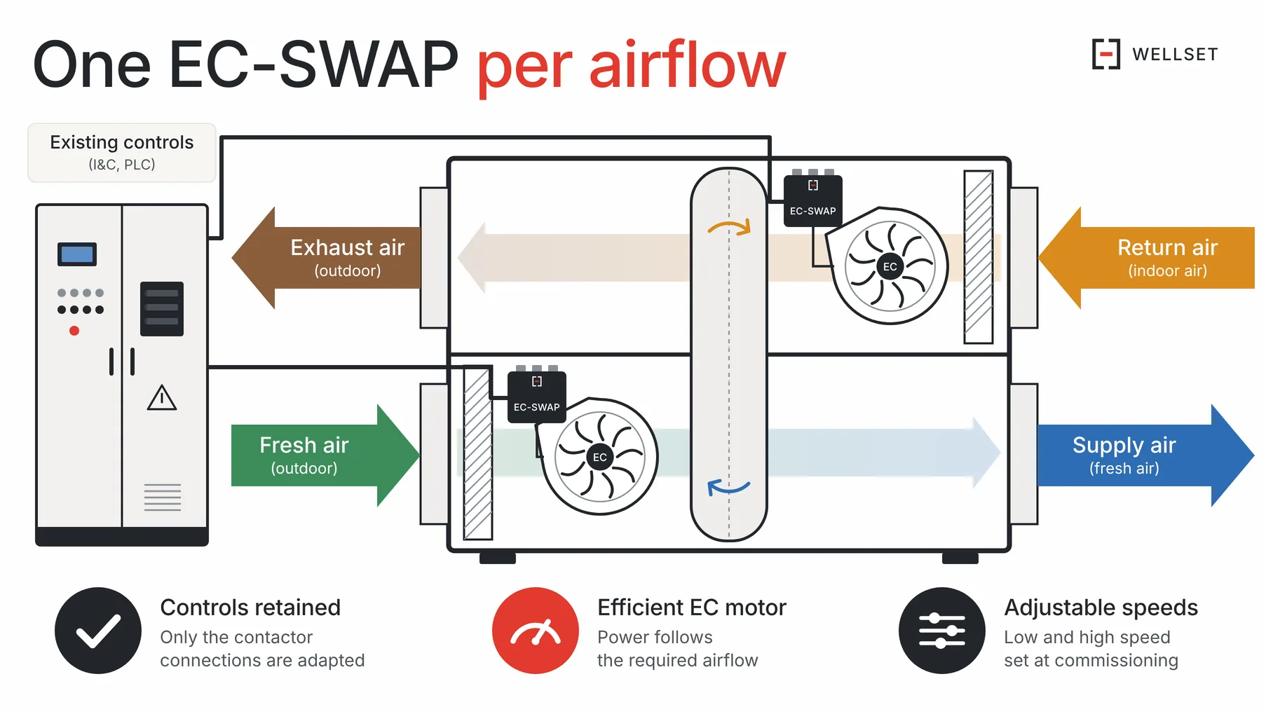
Converts the low-speed / high-speed control of an induction fan motor into EC motor control. The existing control system stays in place, with no controller reprogramming. One module per airflow.
The film
The film goes through the “automation” and “electrical wiring” lines of a retrofit quotation one by one, then shows what is left with EC-SWAP. 58 seconds, no sound needed.
Specifications
| Manufacturer part number | WW-EC-SWAP-1 |
|---|---|
| Function | Conversion of a two-speed induction motor control into EC motor control |
| Rewiring | Contactor connections adapted, I&C system retained |
| Unit | One module per airflow |
| Operating logic | Low speed or high speed, taken from the existing control |
| Speed setting | LOW and HIGH potentiometers on the board, from 0 to 100 % |
| Low-speed / high-speed supply input | 400 V AC three-phase without neutral, 50 Hz |
| EC motor supply output | 400 V AC three-phase without neutral, 50 Hz |
| Maximum current | 16 A |
| Fault contact | 0,1 A maximum |
| Protection | Overvoltage and overcurrent, replaceable 0,5 A fuses |
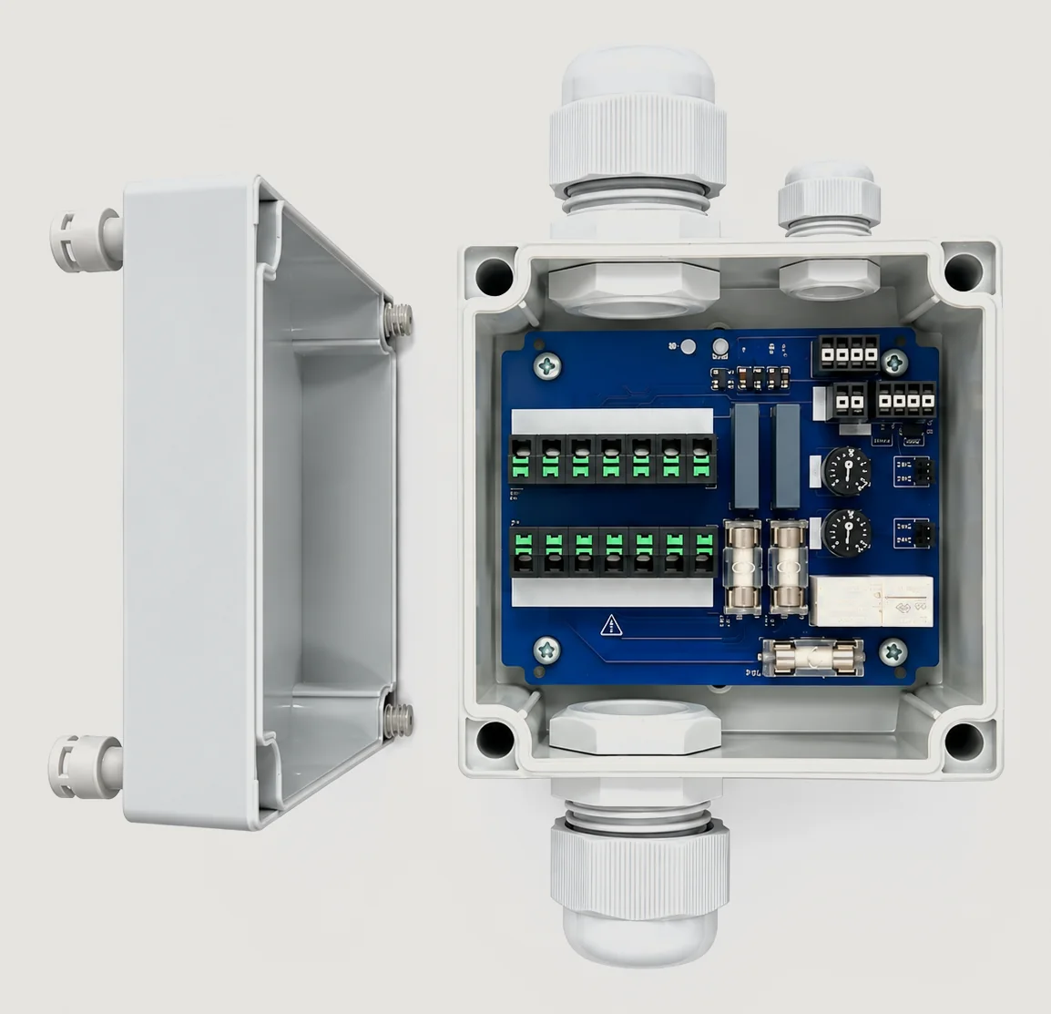
| EC motor logic port | 4-pole terminal block · supply 24 V DC 25 mA · control 0–10 V max. 1 mA |
| External controller logic port | 4-pole terminal block · inputs ±30 V DC maximum |
| Connection cross-sections | Solid 0,5–2,5 mm² · stranded 0,5–1,5 mm² · stripping length 9–10 mm |
| Ingress protection | IP65 |
| Dimensions | 130 × 130 × 75 mm |
| Mounting | Wall-mounted, with screws (not supplied) |
| Compliance | EU declaration of conformity of 5 Oct 2026 · WEEE Directive 2012/19/EU |
| Industrial property | Patent pending · CH000473/2026 |
| Manufacturer | Wellset |
| Restocking lead time | Confirmed in the quotation |
What the module changes
LOW and HIGH are set from 0 to 100 % at commissioning: the power drawn follows the set airflow.
Speed drops with airflow, and noise with it.
The control system and existing command stay in place, with no reprogramming. Only the contactor connection is adapted.
Each module has its own two potentiometers: supply and extract are set separately.
Connection
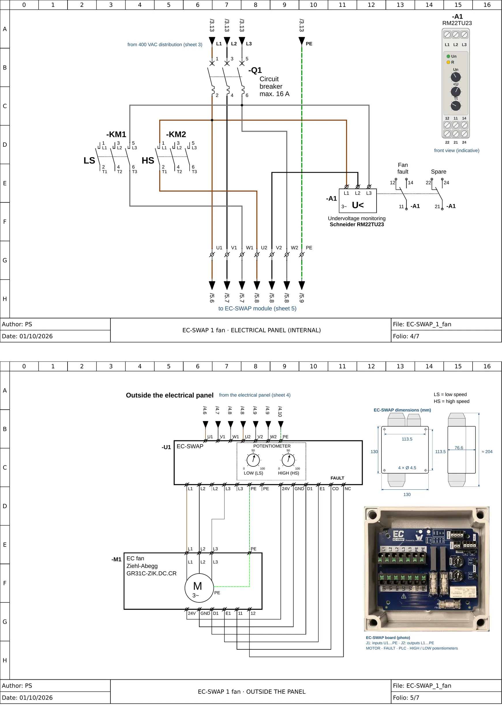
The module is mounted inside the air handling unit, as close as possible to the fan. Each contactor now switches one phase only: low speed on W1, high speed on U2; U1, V1 and W2 are taken downstream of the circuit breaker. The module draws the EC motor supply and its 24 V DC from them, generates the 0–10 V setpoint and returns the fault contact to the control system. One module per airflow.
The wiring on video
The existing two-speed motor cable connects as is to the PV-GV input; the output feeds the EC motor with 400 V three-phase, no neutral.
Terminal block J3 “MOTOR” is wired terminal to terminal, each label to the same label (24V · GND · D1 · E1); the motor fault signal arrives on J9 “FAULT”. The motor output stays live: a stopped motor is not de-energised.
98 seconds, no sound.
Before / after
Before: an induction motor with two fixed speeds. After: EC-SWAP sits between the existing feeders and the EC motor; the control selects the speed, the module translates it into a 0–10 V setpoint.
What changes: the connection of the contactors, one module per airflow. What stays the same: the control system and the controller program.
54 seconds, no sound.
Schematic diagram
Circuit folio and layout overview, to browse in your browser.
Open the schematic diagramReplacing a two-speed motor
The two ways to do it, what to check before ordering, and EffEl support from electricity suppliers.
Read the guideFrequently asked questions
Does the electrical wiring or the control system have to be modified?
Not the control system: no controller program is touched. In the cabinet, each contactor now switches one phase to the module, as per the wiring diagram.
How is the air volume controlled?
With the LOW and HIGH potentiometers on the board, flow by flow, or with a setpoint from the controller on the logic port. Sensor-based variable airflow is the EC-SWAP-PRO function, available in 2027.
Does the installation require a prolonged ventilation shutdown?
No: motor replacement, module mounting and setting of the two speeds, one airflow at a time.
Does a renovation with EC-SWAP count for EffEl support from electricity suppliers?
Not on its own: as long as the control stays at two speeds, the SFOE does not count the motor change. On a system less than 15 years old, the change to sensor-based control with EC-SWAP-PRO (2027) falls under measure LU-01b. The electricity supplier decides.
Is EC-SWAP patented?
A patent application has been filed in Switzerland (CH000473/2026, 2 Apr 2026). An EU declaration of conformity dated 5 Oct 2026 covers the EMC, low-voltage and RoHS directives; the module also falls under the WEEE directive 2012/19/EU.